|
Applied Methodologies, Inc.
|
Technology Consultation and Research
|
|
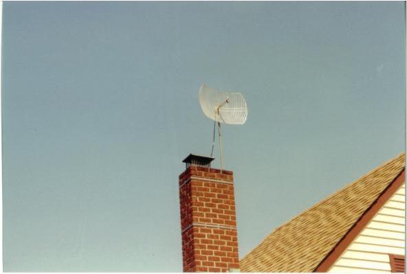
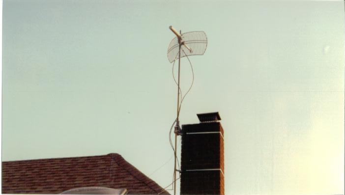
This is a shot of my semi final configuration. I was able to use a 5' and a 2'.4" section of mast screwed together then attached to the rotor giving me the optimal 7' of height over the homes for stumbling and PtP and PtMP testing. The 4" was the space for inside the rotor mount. This seven foot section has been in operation flawlessly through storms since late April. With a serious wind load it moves less than 1 inch.
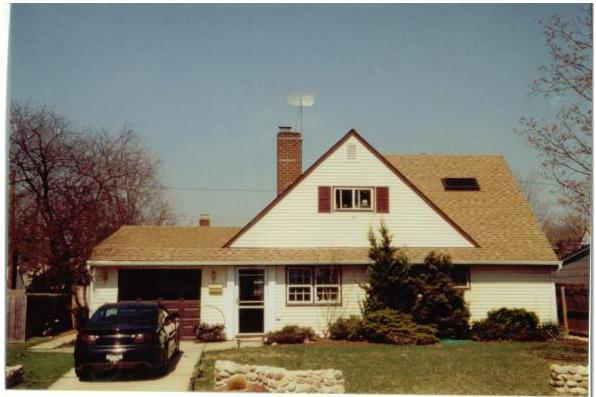
Here is another shot of the semi final setup. The antenna rotor's starting direction and the antenna point due south.
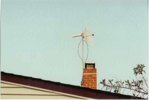
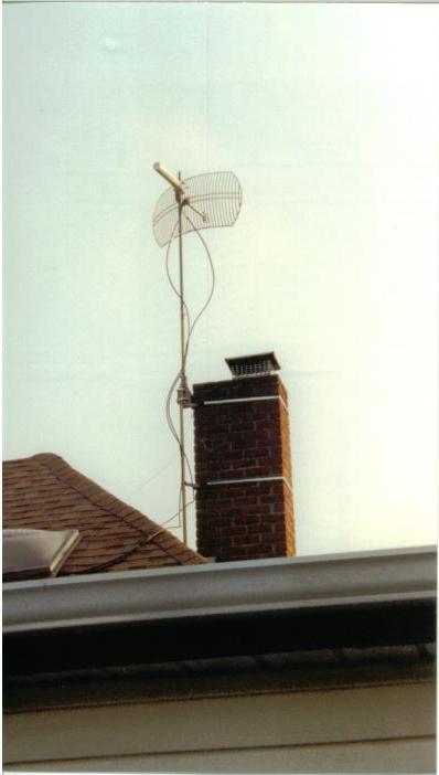
After several weeks of using and testing the new rooftop stumbler setup I decided to add a Max Rad 15dBi WISP Yagi antenna. With a little extra height and the beamwidth I can hit more homes in a closer range, and I did plus I can also test additional PtP links. I do not get the distance like the Mag grid but when the 1 watt amp is used on either one I picked up a plenty of APs.
Here is another shot with both antennas mounted. You would not believe the side lobes from both of them. I only use one at a time, yet the side lobes are wide enough to pick up an AP a couple of doors down.
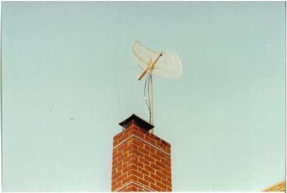
Here is a good shot of most of the RF circuit with rotor and mast.
Here is a shot of the cables going into the skylight. I can still close the skylight for security and weather reasons. I do NOT have any lightning arrestors hooked up. For each antenna has its own 2' section of cable then I add a 25' section into the lab. I left plenty of sway and turning room. All cables are secured with plastic tie straps to the mast at several locations that you may not see. When not in use in the lab the cables are disconnected and hung in a secure location or I have the end connectors capped and I leave the cables coiled outside the skylight. I shall eventually add lightning arrestors to the RF circuit, once I setup the grounding.
|
||||||||||||
|
|||||||||||||